MIE243
CNC MACHINE
One of the projects I took on as part of the MIE243 Mechanical Engineering Design course is to create a CNC Machine. At first, this group project may seem quite complicated. Where would you even start with something like this? However, after breaking down the problem, it becomes much easier to tackle such a large challenge. Take a look at how our group worked together to create a CNC Machine for a hobbyist machinist!
Defining the Project Specifications
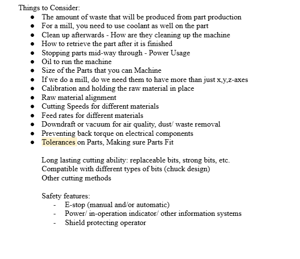
The first thing that our team did was define the project specifications. We needed to define who our CNC machine was for, and what our CNC machine could do. How much did we want our project to cost? What materials did we want our machine to cut? There were several factors to consider for the project.

Candidate Designs
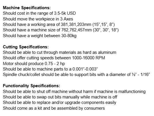
After our team defined the project and did market research on existing CNC machines, our team then proceeded with creating candidate designs for a CNC machine. During our team meetings, we made sure to talk about which components we wanted to use so that our designs did not overlap with each other too much. Furthermore, we made sure to provide feedback to each other to ensure that our designs were feasible.


Amen, Harrison, and I created the first 3 candidate designs. We brought these designs to our first check-in with our TA. After the check-in, the team further iterated on the candidate designs to create 4 more candidate designs, therefore leaving us with a total of 7 candidate designs. We also did a TON of research to make our final 4 candidate designs more detailed and better represent what our final (for this course) conceptual design would look like. The research we have done allows us to justify our design choices for our conceptual design.
CAD and our Conceptual Design
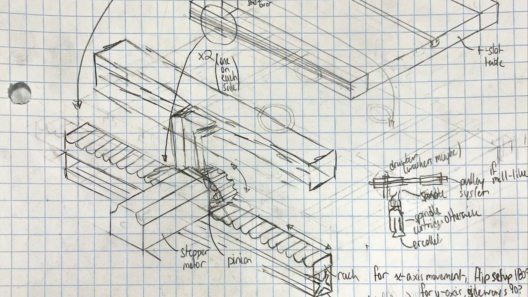
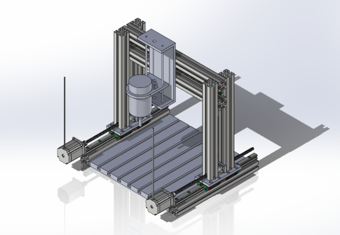
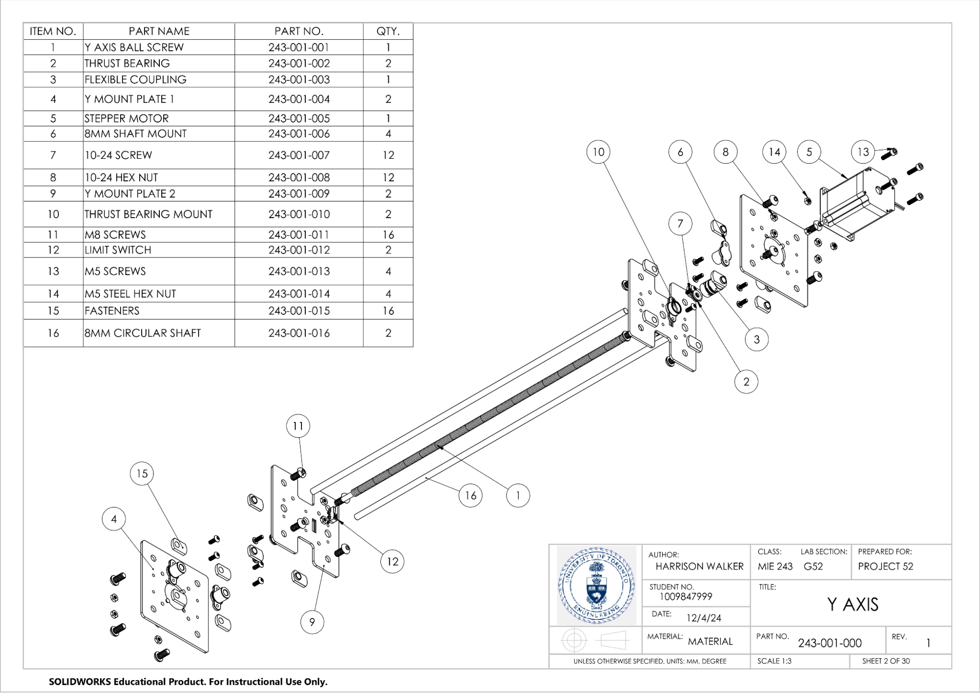
Once we had our candidate designs, our team then worked to determine our final conceptual design. During this process, our team tried to think about the various tradeoffs for using certain parts, and why we may want to use certain features over others. For example, our team decided to use ball screws for x and y-axis movement because there would be minimal backlash. We also decided to use stepper motors over other motor types to reduce backlash and improve accuracy in small movements. Our team then started creating our CAD model for the conceptual design using Solidworks.


Analyzing my Teamwork Skills
During my APS111 and APS112 course, I used the ITP metrics system to analyse my teamwork, provide effective feedback for my peers, and receive constructive criticism to make myself a better teammate. In the past, the general consensus I have found with my feedback is that I am an alright teammate to be around in terms of having fun, but when it comes down to focusing on doing work, I am not as focused. Therefore, for this course, I wanted to make sure that I am not only did I have a lot of fun with my team, but I also wanted to make sure that our team also got as much work done as possible.

During this project, I feel like I have somewhat taken a bit of a leadership position. This is not really what I had in mind when I started the project. However, when forming groups, Harrison was away at an event. This led to me meeting Amen. Additionally, when we were looking for a fourth member to join our team, I somehow ended up contacting Rahima. I guess that in some way, I have acted as an intermediary in terms of communication, and if that makes me some form of leader, then I am fine to take that role. However, I would prefer to tell people that I just make sure everyone is on the same page.

Ultimately, I hope that I am continuing to grow as a person throughout these group projects. One thing I try to do whenever I am working with the team is we will go and play Connections, just as a way of working together to achieve a common goal. You can call me a bit biased, but I personally think that we are getting pretty good at Connections. In all seriousness, I hope that by trying to stay positive, even in the hardest of times, I can encourage my team to put their best foot forward and make this project a success. And when I see my teammates working so hard to complete their tasks, it only makes me want to work harder to help make their work stand out! Hopefully, our hard work will come together and this project will be a success!
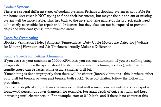
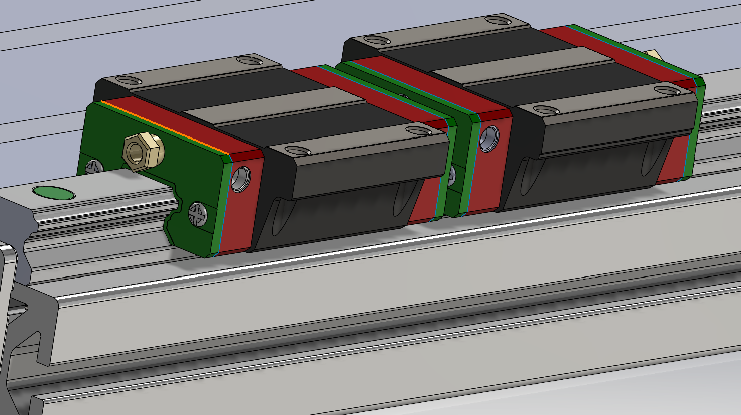
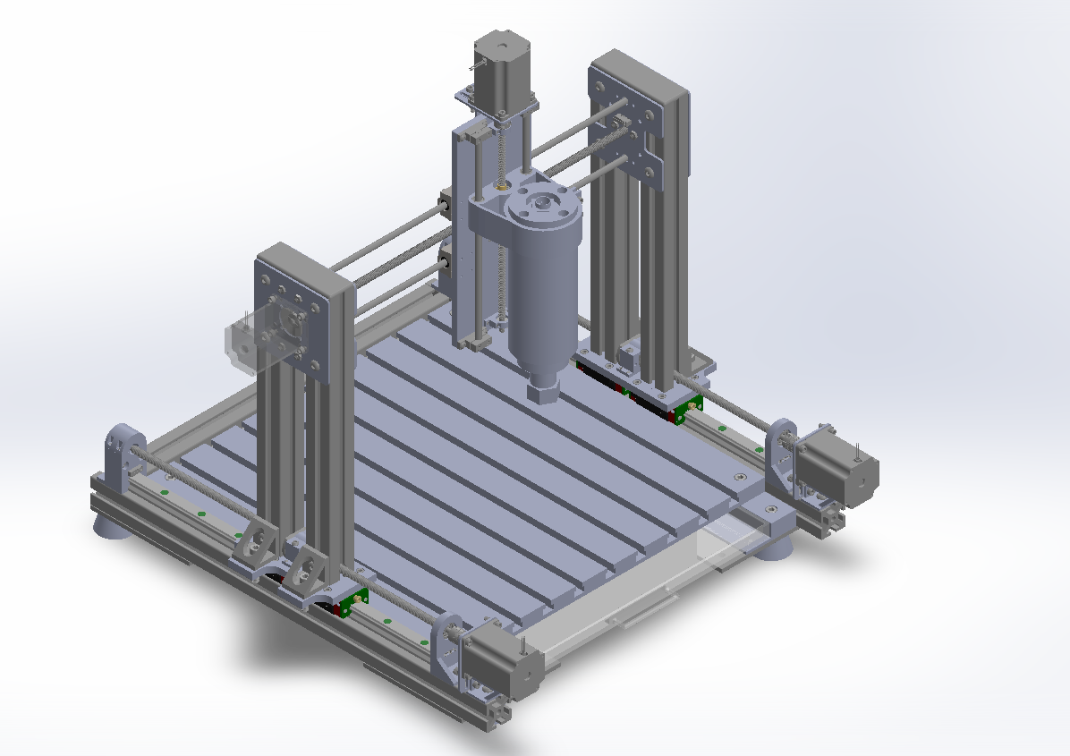
The Final CAD Model
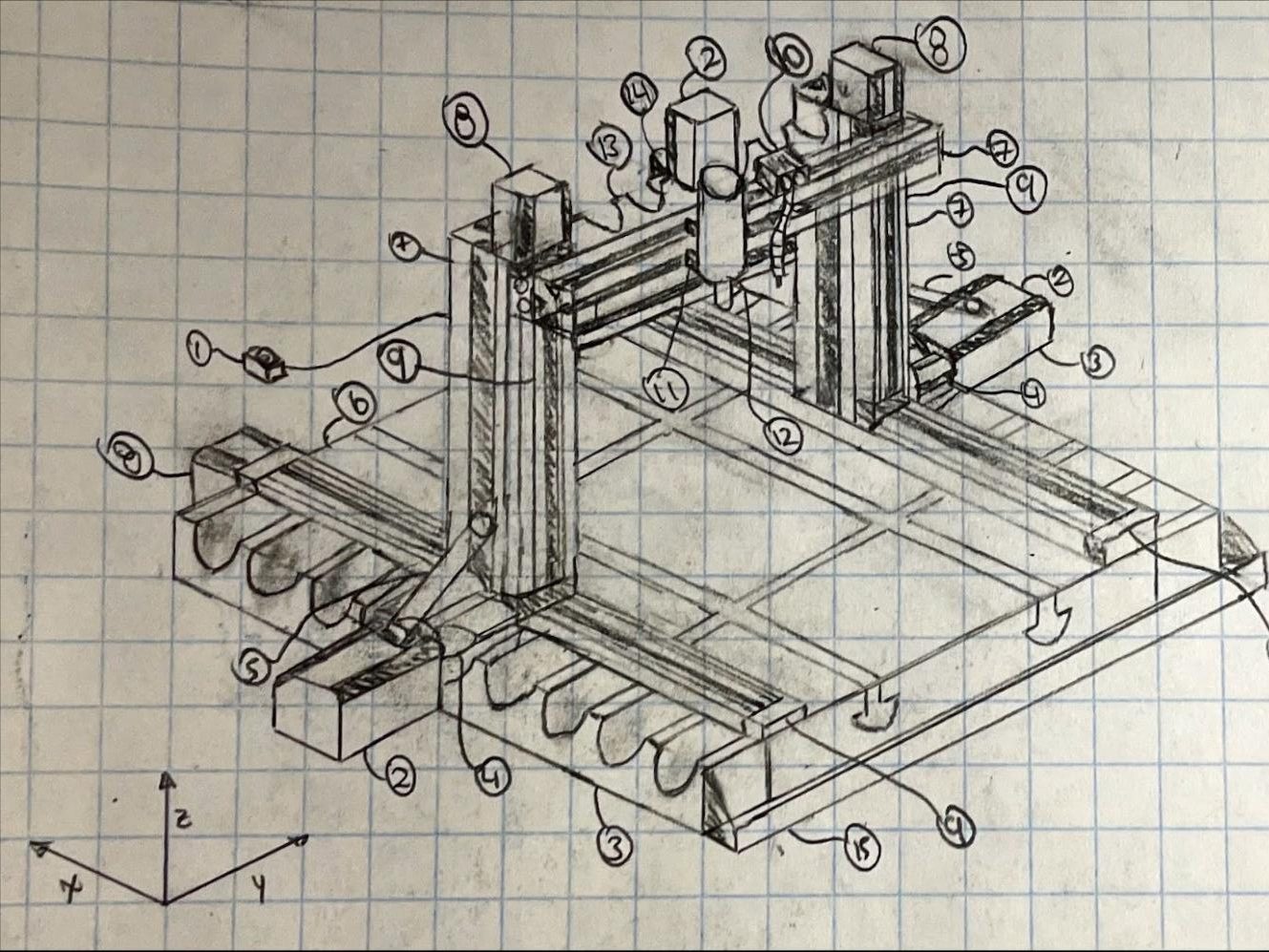
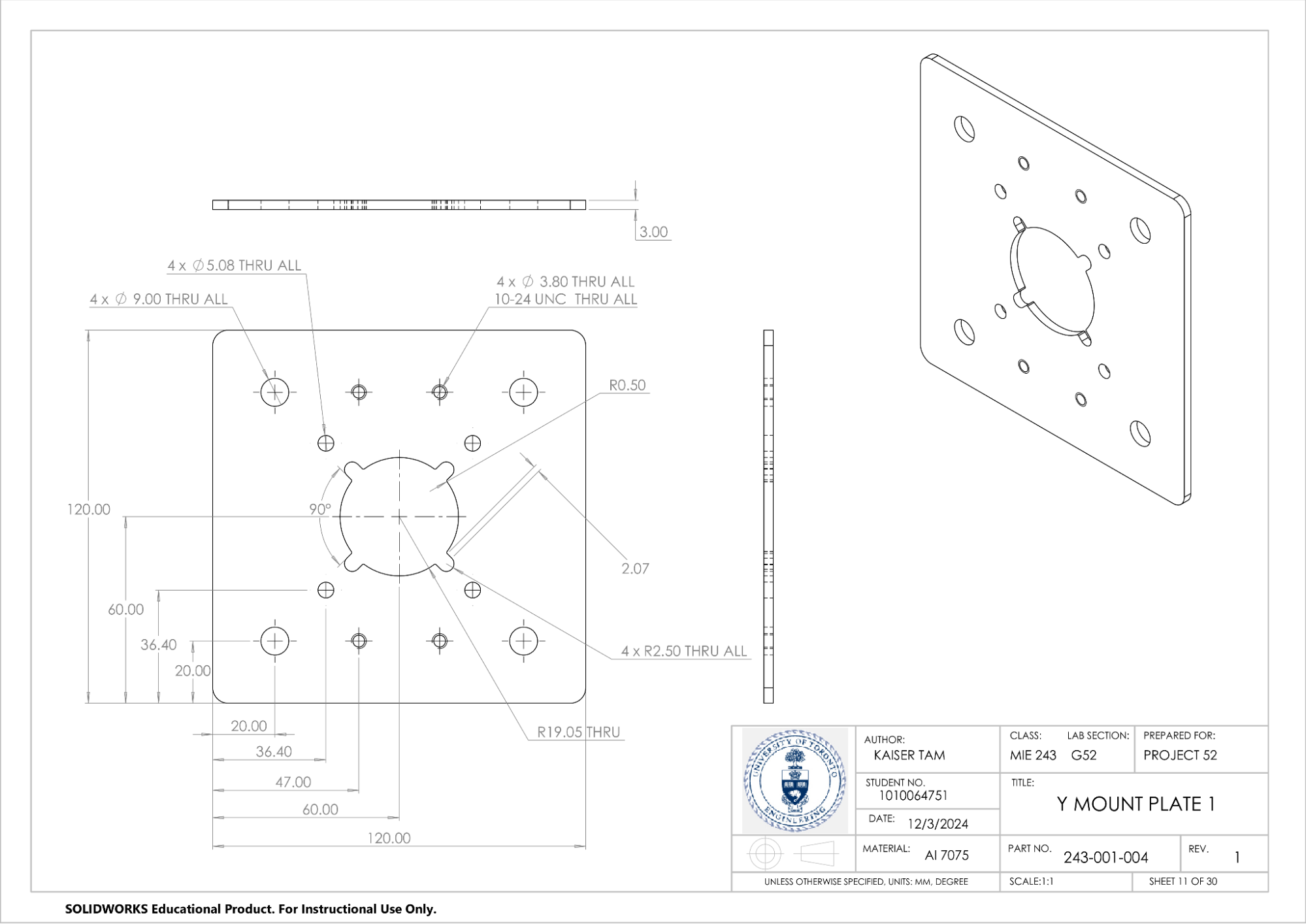
To create the final CAD Model, our team split up the CNC Machine into several subassemblies. This served two purposes. First of all, this made the workload easier as each team member could work on a specific subassembly and find parts for their subassembly, which meant that we would make more progress on the CAD model at the same time. More importantly however, this ensured that Solidworks was less likely to crash as there was less stress on each person’s computer at a given time. Each subassembly contained several components; some were custom, made by the team, while others are off-the-shelf parts. These subassemblies come together to create our final CAD model.
And so, that is our CNC project. For future MIE243 students, I hope that this CNC machine project page was insightful, and you are able to take something from it (not literally, that would be plagiarism, don’t do that), and I hope that you can make your project better than ours was, with the knowledge gained from this page. This project taught me a lot about Solidworks drawings and assembly, and about proper engineering documentation.
