Blue Sky Solar Racing

In my second year at UofT, I joined the UofT Blue Sky Solar Racing team as an aerodynamics member. The Blue Sky Solar Racing team has competed in various competitions such as the American Solar Challenge, Formula Sun Grand Prix, and the World Solar Challenge in the challenger class. For more information about Blue Sky Solar Racing, you can check out our website or our Wikipedia page!


The Aero Design Process

The first thing that I did as a part of the Blue Sky team is recruitment. During aero recruitment, we essentially learned about the general workflow for aero team members. This consists of CAD, meshing, and simulations. CADing at Blue Sky is done on CATIA Generative Shape Design. CATIA is useful for designing aerobodies as we can use the multi-section surface tool to create aerodynamic surfaces. Furthermore, identifying sharp edges where there may be increased drag or turbulence. Fidelity Pointwise is used for meshing, which is where the shape of the aerobody is accurately defined for running computational fluid dynamics (CFD) simulations. Finally, simulations are done using ANSYS Fluent. Thankfully, the Blue Sky Solar Racing has created a script, which has helped the team ease into using ANSYS for work. I am really glad that I got to learn different CAD software such as CATIA, as there are some mechanical engineering design jobs that do prefer prospective employees learn CATIA. Furthermore, learning ANSYS is a great skill to have for being attractive as a prospective mechanical engineering intern.

CAD using CATIA Generative Shape Design. The shape of the actual aerobody is generated using a script on Microsoft Excel. Some things to keep in mind while CAD’ing include the fact that somebody has to mesh the car afterwards, so there must not be any holes in the CAD, and that the vehicle must be as aerodynamic as possible, so the design must minimize aerodynamic drag.
Meshing the vehicle. This step involves defining the geometric shape of the car using triangles and quadrilaterals, which divides the car into continuous cells. This is important for when simulations are done on the vehicle. If you wanted to calculate the coefficient of aerodynamic drag for the vehicle, it would be a difficult calculation to just calculate it in one go. That is why we use a mesh to divide the vehicle into tiny areas. Think back to Riemann sums, and how as the number of partitions increases, the accuracy of the approximation increases. This work similarly with meshing; as the mesh gets finer, the simulation results get more accurate.
Results of running a computational fluid dynamics (CFD) simulation using ANSYS Fluent. Blue Sky’s script allows multiple people to simulate their meshes at the same time, which is great for saving time. Simulations take a lot of time in general, so we try to run sims overnight. During this sim, I simulated the Gen11 vehicle, Borealis, along with a canopy design that I created. The values from the simulation are given in the spreadsheet, but they are simply taken from the ANSYS results.

In my time on aero, I have done the same CAD, Mesh, Sim process countless times for various projects. As I have gone through this iteration, process, I have refined my ability to use each of Catia Generative Shape Design, Pointwise, and ANSYS Fluent. At first, I was quite clueless when it came to CATIA. It felt so weird to use a different CAD system than SolidWorks and it really challenged the way I thought about CADing. However, learning to do both surface modeling in CATIA and solid modeling in SolidWorks provides the benefit of seeing how different parts can be designed using the two techniques, and then choosing the approach that best allows me to capture the geometry of what I am CADing. As for Pointwise, In Pointwise, I’ve learned to deliberately troubleshoot and refine meshes instead of just doing what a tutorial said was good. Learning why certain things work like using growth spacing vs tanh spacing for certain connectors, or when to set the full t-rex layers to 1 or 0 really makes a difference in the quality of meshes I was producing. The more accurate the mesh is, the more accurate the sims will be, so it was critical that my meshing ability gets refined.


CAD Process

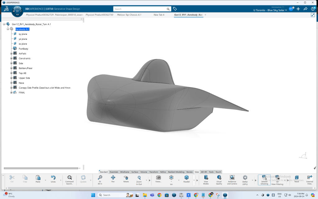
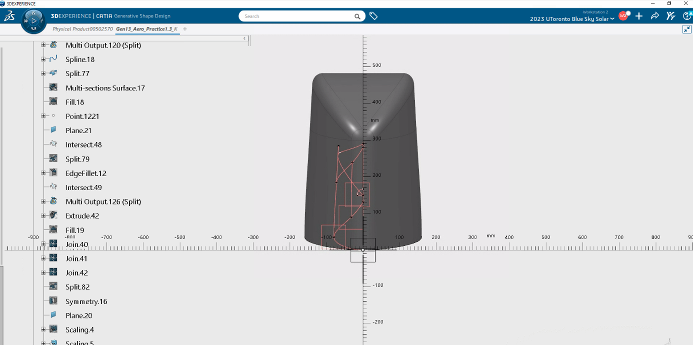
This section will go over how I like to use CATIA to do surface modelling to create potential solar car designs. CATIA is great for solar car design because the multi-section surface tool lets me create smooth surfaces based on specific supports and guide profiles. Furthermore, CATIA allows me to iterate quickly on my previous designs so that I can make adjustments to my CAD as necessary.
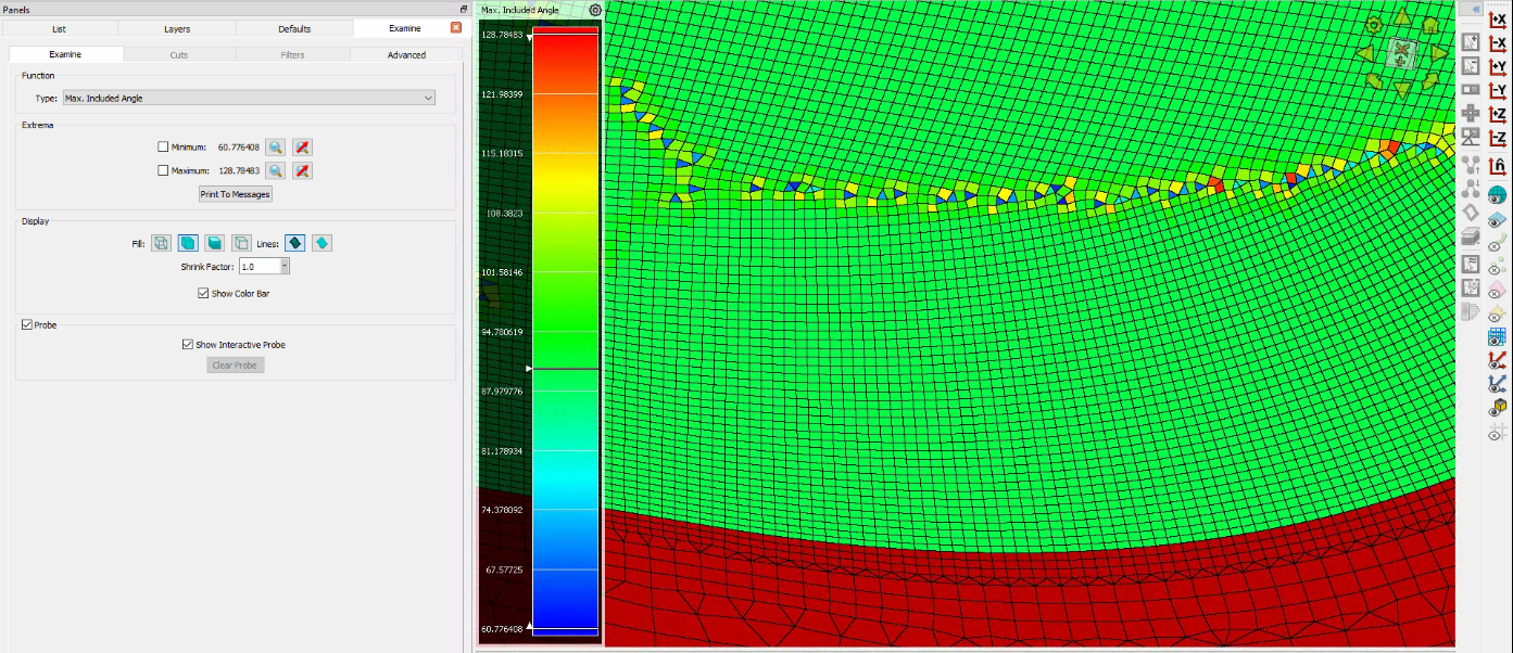
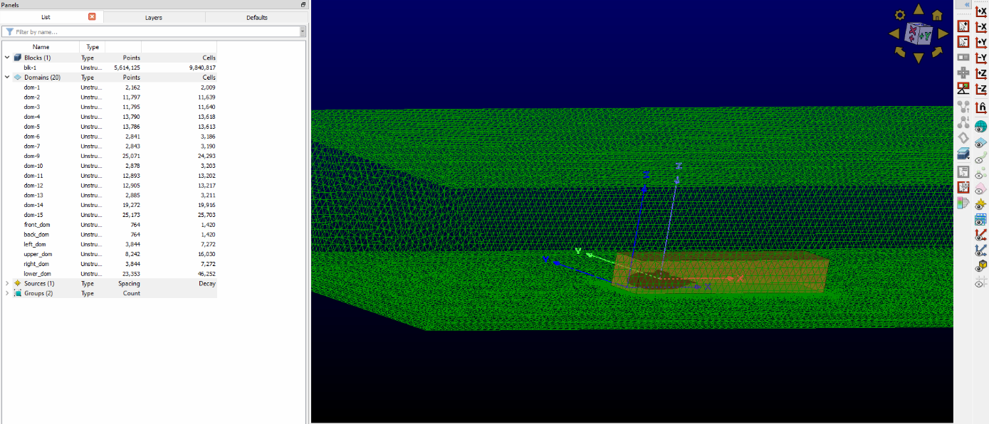
The first thing to consider when creating the solar car is what airfoils I want to use. The types of airfoils chosen will determine how the solar car performs, and whether the car is well designed. To select airfoils, we use JavaFoil to create a 301 by 2 list of points on the x and y axes. This creates the shape of the airfoil, which is then scaled up in Excel so that points cover a 5m chord length. From there, airfoil points can be added to CATIA using a script.
One I have airfoils in CATIA, I can then work to create the bottom half of the car. First, I will decide how far I want my car to extend out, and will decide what shape I want the bottom of the car to be, depending on the wheel placement and where the driver will sit. Then, I will extrude two planes and trim them with each other.
Next, I can then work on the top of the car. After adding in the details for the license plate, I can then determine how tall the car will be. Then, I can use splines to create the upper side shape. My goal here is to make sure that there are no sharp edges.
After tapering the nose portion to get a well rounded nose, I am now left with half of the aerobody!
Once the main body has been completed, I can then work on adding appendages and the canopy. The canopy is in my opinion, the hardest part of a car. You can see the splines and planes I used to create the canopy in this image here. However, I made this canopy way too small, so I had to scale the size up, and that is what you see in this image.
At this point, the only thing left to do is to attach the canopy to the rest of the aerobody and add fillets to smooth out the edges. At the end, I am left with this aerobody, which is ready to be meshed using Pointwise and simulated using ANSYS Fluent.

Meshing Process

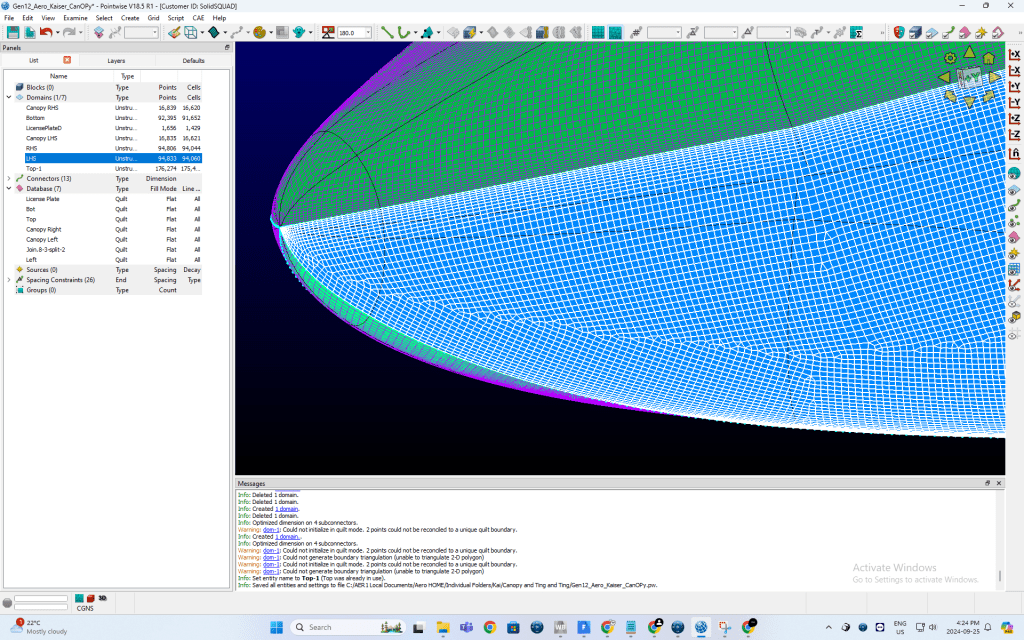
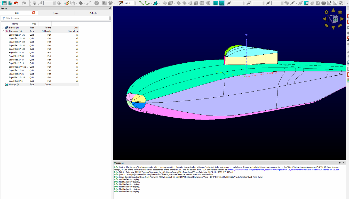
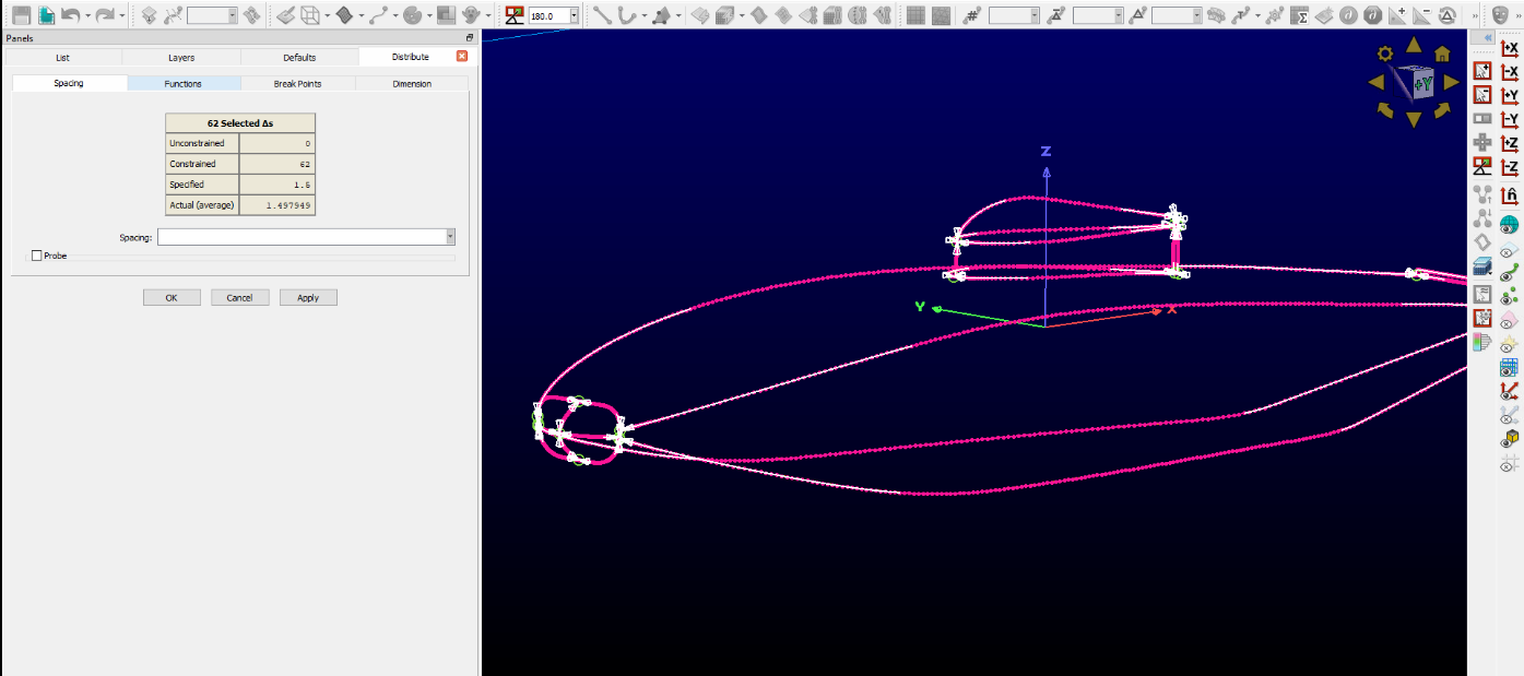
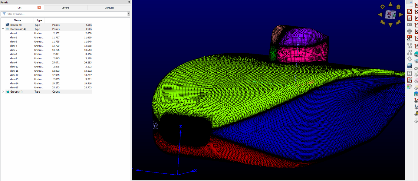
Once the CAD is complete, it is time to mesh the car. Since vehicles have a complex shape, and hand calculations would be tedious, it is important to create a mesh that accurately represents the car’s geometry to prepare it for a computational fluid dynamics sim on ANSYS. If the mesh is poorly done then the car may not sim at all. And if the car does sim with a poorly constructed mesh, the finite volume method will inaccurately predict important aerodynamics values.

This is Pointwise. The first thing I will do in Pointwise is combine my databases into specific sections of the car, such as the license plate and the array. I like to split up the nose by top and bottom, and I also like to split the canopy as shown in the image above.
Once the domains are created, the next step in the meshing process is to create connectors on the database entries. This is the stage where you place points at key geometric features (ends of CAD edges, corners) and turn those CAD edges into connectors with a chosen point distribution. You then assign spacing laws (geometric, or tanh bias) to ensure matching point counts on mating connectors for structured topology, and equivalence/merge shared endpoints so intersections become single nodes.
With connectors finalized, you can form domains and proceed to boundary-layer extrusion (e.g., T-Rex). Domains are the 2D mesh regions bounded by connectors and mapped to CAD surfaces; they define where Pointwise will generate surface cells. In the image above, I’ve reshaped the domains to better follow the car’s curvature and feature lines, which improves element alignment, reduces skew near tight radii, and sets up cleaner boundary-layer extrusion and smoother transitions into the volume mesh.
T-Rex layers extrude high-aspect-ratio cells off the surface so the first few quads (from split tris) are small near the wall and then grow progressively larger into the freestream using a specified growth rate. This gives tight resolution for boundary-layer gradients while keeping the outer mesh economical.
I check mesh quality with a maximum included angle target <140°, tightening it near curvature changes so quads/tris don’t fold or distort. If a region violates the limit, I adjust connector spacing, bias, or domain topology to pull angles back under 140° without flattening the geometry.
Finally, once the surface domains are complete, I run a script to build a far-field box around the car. I then create a volume block and grow the surface T-Rex layers, ensuring clean transition to the far field. Before export, I assign boundary condition names and write the mesh for Fluent.

Wind Tunnel Testing

One of the first things I got to do as part of the Blue Sky team is help with aero validation. We wanted to do this to compare our simulation results from the Gen 11 vehicle on ANSYS Fluent to actual values. To do this, the team went to the Ford Drivability Test Facility (yeah, it’s called DTF) Wind Tunnel No. 8 to test out the Gen 11 vehicle, Borealis. It was really cool to go to the Ford Drivability Test Facility because it provided insight into a potential career for a mechanical engineer that also involves aerodynamics.

One of the many computers, running simulations. It was really cool to tour the Ford DTF facility, as it was great to see how Ford does their workflow and tests their vehicles.
Inside the Ford DTF Wind Tunnel No. 8. The pink strings you are seeing on the car are tufts, which are used in tuft visualization. During wind tunnel testing, the solar vehicle is placed on the circular platform and strapped down using ratchet straps. This ensures that when the fan is blowing, the car does not change position, and an accurate value can be calculated.
Tuft visualization. Air is hitting the nose of the car. You can see the solar array area is quite aerodynamic, and that there is some turbulence after the first wheel fairing towards the bottom of the vehicle. We eventually tested our vehicle at speeds up to 70kph, at a max yaw angle of 57 degrees. When we increased the yaw angle past 28 degrees at a speed of 100kph, the front right wheel fairing popped off. This was partially due to us forgetting the part to hold the wheel fairing, but it is also due to air coming up underneath the vehicle and popping the wheel fairing up.
Laser sheet flow visualization. Propylene glycol is used to create smoke, and then a class 3 laser is shined at a specific angle to make the smoke appear green. In this image, the yaw is set to 0, and we are looking to see the flow around the canopy.
More laser sheet flow visualization, this time on the left side of the vehicle. When we did laser sheet flow visualization, we reduced the wind speed to allow for a person to hold the propylene glycol smoke gun perpendicular to the car. Laser sheet flow visualization was one of the coolest things I saw.

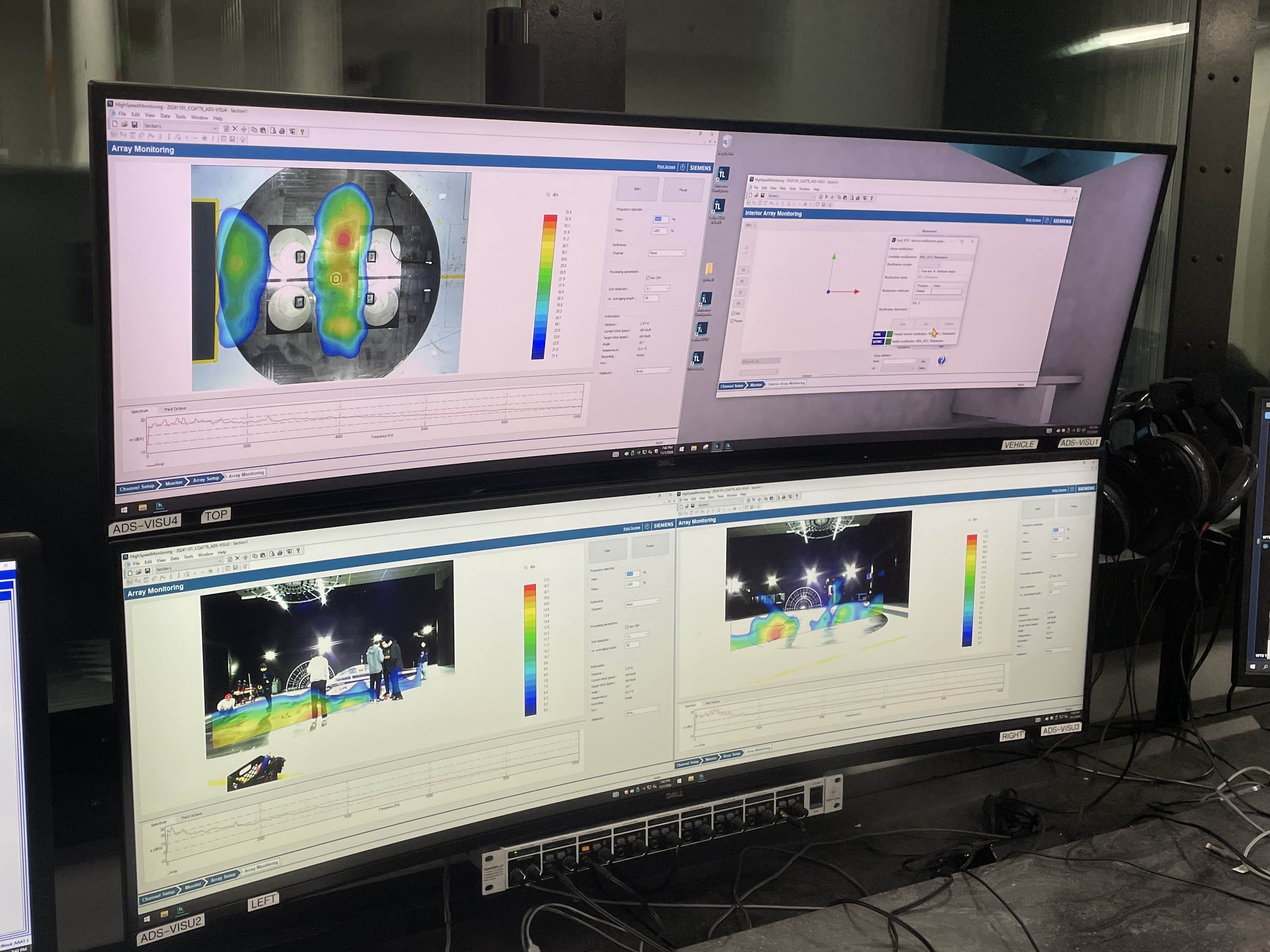
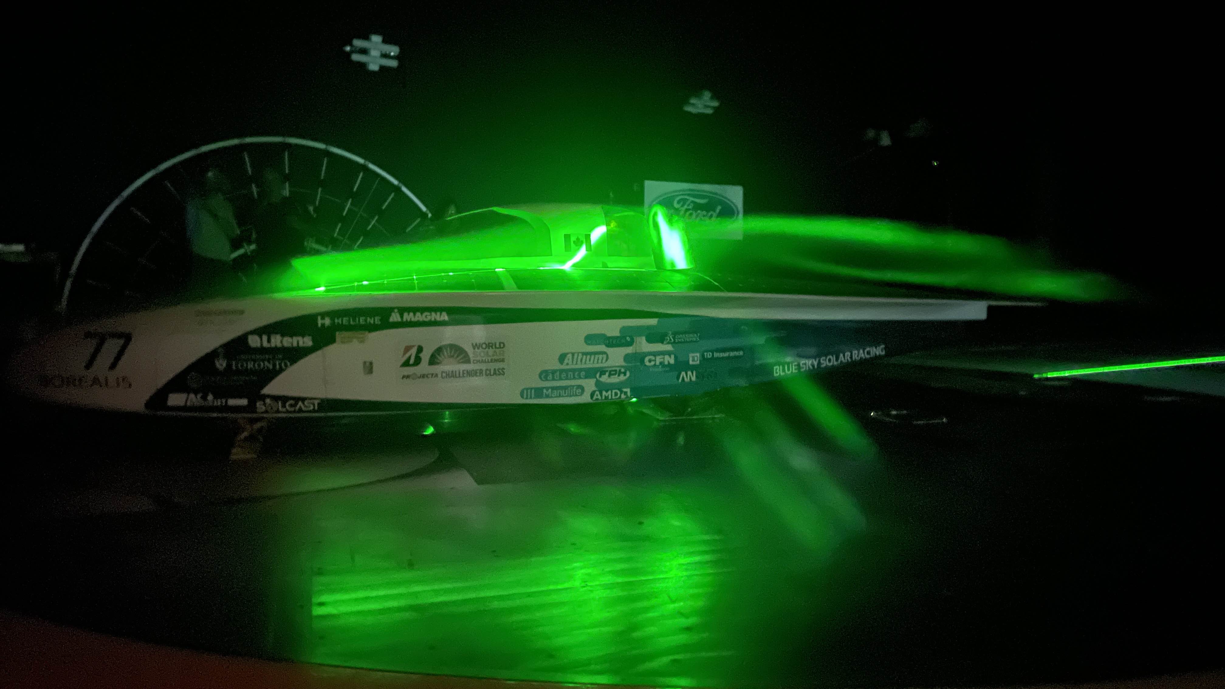
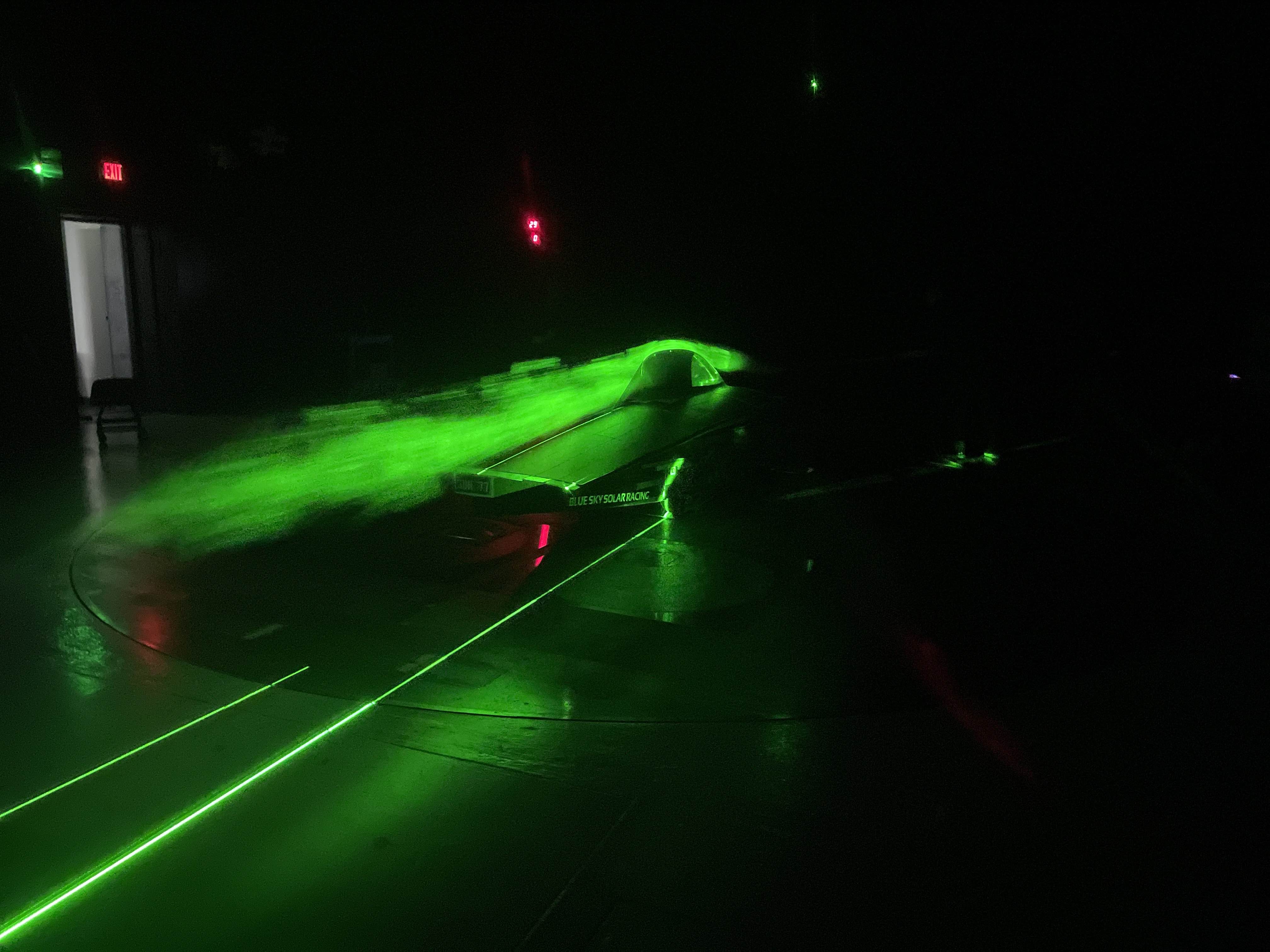
After completing the wind tunnel testing, our team then went back to Toronto to report on the results of the testing. The wind tunnel testing provided significant insight into how our CFD model compares to real-life results. This report will provide future generations of Blue Sky Solar Racing with data on force measurements at varying speeds and yaw angles to make design improvements on future solar vehicles. Areas for aerodynamic improvement are identified based on the observations made during the tuft and laser sheet flow visualization.